







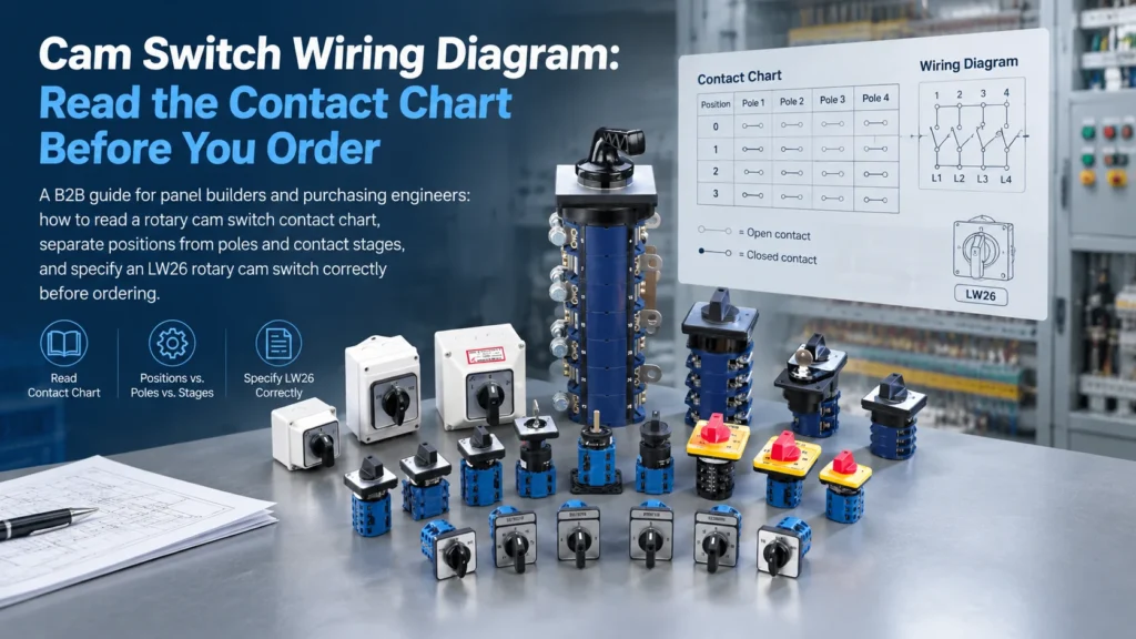
Two rotary switches can have the same handle, current marking, and 1–0–2 faceplate while performing different electrical functions. That is why a cam switch wiring diagram should be part of your purchasing specification, rather than something checked only when installation begins.
For panel builders and equipment manufacturers, the important question is simple: which contacts close at each handle position? A clear answer helps prevent ordering a switch that fits the panel but does not match the circuit.
This guide explains how to read a contact chart, separate the switching function from the terminal layout, and prepare the information needed for an LW26 rotary cam switch enquiry.

What a Cam Switch Wiring Diagram Actually Shows
A cam switch drawing may contain three different types of information. Read them together, because each answers a different question.
| Drawing or chart | What it tells you | What to check |
|---|---|---|
| Contact chart | Which contact pairs are open or closed at each position | Whether the sequence matches the intended control function |
| Connection diagram | Terminal connections and any specified links | The exact terminal numbering and required bridges |
| Mechanical drawing | Mounting holes, dimensions, and available space | Whether the chosen configuration fits the equipment |
The faceplate describes the operator’s choices. It does not, by itself, establish the internal circuit. Likewise, a photograph of the rear terminals cannot reliably identify the complete contact sequence.
Positions, Poles, and Contact Stages Are Different
Three positions mean the handle has three selectable settings. It does not mean the switch has three poles. Poles describe the circuits switched by the specified function; stages or layers describe the stacked contact sections that implement that function.
For example, HAND–OFF–AUTO has three operating positions, but its control logic might need only two independent contact pairs. A three-phase ON–OFF switch has two positions while switching three power conductors. Count the required electrical paths from the circuit, rather than from the labels on the handle.
How to Read a Cam Switch Contact Chart
1. Identify the positions and the viewing direction
Start with the handle positions shown on the drawing: for example, OFF–ON or 1–0–2. Check whether the illustration is viewed from the operating side or the terminal side. A reversed viewing direction can lead to mistaken assumptions about left and right positions.
Also confirm the rotation angle and whether each position is maintained or spring return. A switch that returns to centre after release behaves differently from one that stays in the selected position.
2. Follow each contact pair across the chart
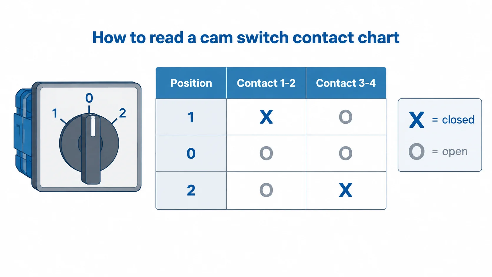
Read the manufacturer’s legend before interpreting marks such as X, dots, or shaded cells. Then trace each contact pair across every position. The aim is to produce a plain-language description: “this pair closes in position 1 and remains open in positions 0 and 2.”
In some manufacturers’ charts, an X marks a closed contact and a line joining marks indicates that it stays closed between positions. Those conventions must be checked against the drawing’s own legend. A number beside the contact identifies a terminal; a number or word on the faceplate identifies a handle position.
Do not assume that a numbering convention from another switch brand or another function code applies to your chosen unit.
3. Read a Published HAND–0–AUTO Contact Chart
A useful reference is Eaton’s T0-2-15432/IVS, catalogue number 041229. Its official product information identifies a maintained HAND–0–AUTO function and provides a corresponding contact chart.
The table below transcribes the four contact columns in that chart from left to right. Column labels describe their position in the drawing, not terminal numbers.
| Position | Column 1 | Column 2 | Column 3 | Column 4 |
|---|---|---|---|---|
| AUTO | Closed | Open | Closed | Open |
| 0 | Open | Open | Open | Open |
| HAND | Open | Closed | Open | Closed |
Technical reference: Eaton 041229, official wiring diagram. This is an Eaton example; it does not establish the terminal connections or contact arrangement of a Cantak LW26 switch.
Notice that each active position closes two contacts. A three-position label alone would not tell you this. Read every contact column, then check the separate connection information, including any bridges. When specifying an LW26 for your own circuit, describe the required function and confirm its corresponding drawing instead of transferring another brand’s terminal layout.
Check the Transition Between Positions
A contact chart may describe the stable positions without fully showing what happens while the handle moves between them. Ask whether the relevant contacts use break-before-make or make-before-break operation, and request the transition details where they affect circuit behaviour.
If the control paths must never overlap, include that requirement in the specification. Closed contacts at the stable positions do not, by themselves, establish the full transition sequence.
A selector function also does not automatically establish suitability for transferring two power sources. Source transfer requires an appropriately rated device and a verified arrangement for that application.
Separate Control Circuit Selection from Load Switching
Before checking ratings, state what the contacts actually switch: a control signal, a contactor coil, or the equipment’s power circuit. These are different duties. A large current marking is not a substitute for confirming suitability at the operating voltage and load type.
For a control panel, record both the switching logic and the electrical duty. This avoids a quotation based on the correct handle function but an unsuitable contact rating.
Using Cantak LW26 Rotary Switches in Your Specification
Cantak’s LW26 Series Rotary Switches include different current ratings and mounting options for industrial switching applications. Use the series page to narrow the physical format, then confirm the exact function drawing for the proposed configuration.
A real LW26 ordering example from Cantak’s catalogue
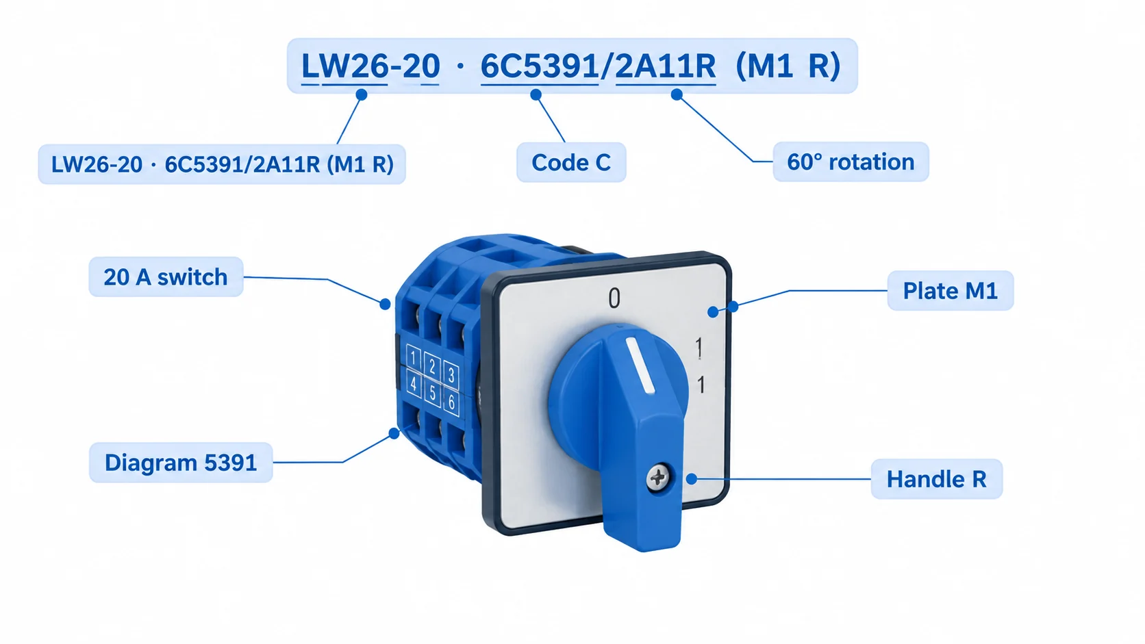
The Cantak LW26 catalogue, printed page 05, gives the example LW26-20 · 6C5391/2A11R (M1 R). Its description specifies a 20 A switch, 60° rotation, character code C, contact-diagram code 5391, an M1 plate, and a black R handle.
The important purchasing detail is the separate contact-diagram code. “LW26-20” alone does not specify the complete switching function. The catalogue’s example identifies code 5391 but does not show that contact chart alongside it; its terminal states cannot be inferred from the code.
For your enquiry, provide the required state table and request the matching drawing. Confirm the final function, stage count, and mounting suffix together before approving a replacement or new configuration.
For projects requiring restricted operation, the LW26S key-lock type switch provides another product direction to discuss. Confirm the permitted key-removal positions and contact sequence for the selected version. A key-operated control switch should not be assumed to provide maintenance isolation.
Start with a matching standard function. Discuss Cantak OEM and ODM rotary switch options if the standard arrangement does not meet the circuit or marking requirements.
What to Send with a Cam Switch Enquiry
- A circuit schematic or a table of required open/closed states at every position.
- Operating voltage, AC or DC supply, and the type of load being switched.
- Required positions, rotation angle, and maintained or spring-return operation.
- Mounting dimensions, panel thickness, and available depth behind the panel.
- Any transition, locking, environmental, or marking requirements.
- Quantity and whether the enquiry concerns a new design or an existing replacement.
For a replacement, send photographs of the old switch, its full model code, and the original drawing if available. Matching only the series name and current value leaves important details unresolved.
Frequently Asked Questions
Can I wire every 1–0–2 cam switch the same way?
No. The front marking identifies positions, while the contact arrangement determines the electrical function. Use the drawing for the exact configuration supplied.
Can a continuity check identify a replacement switch?
On an isolated, disconnected unit, a qualified person can check stable-position contact states. That check does not establish load ratings, insulation performance, or suitability for every transition. Retain the manufacturer’s specification.
What if I do not have the original cam switch wiring diagram?
Provide the equipment schematic, old switch code, photographs, and required position sequence. Ask for a proposed function drawing to review before ordering.
Confirm the Function Before Ordering
A useful cam switch wiring diagram connects the operator’s positions to a clearly defined contact sequence. Checking that sequence early helps purchasing, panel assembly, and engineering work from the same specification.
Need help specifying an LW26 switch? Send Cantak your circuit drawing, position requirements, electrical duty, and mounting dimensions to discuss a suitable configuration.