


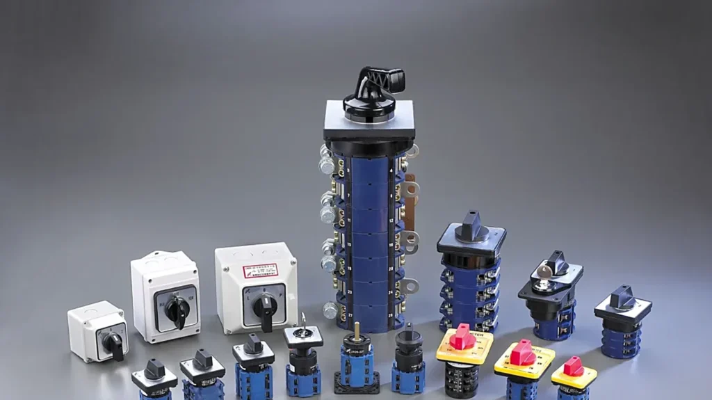
Choosing between rotary switch types is usually framed as a question of appearance, and that is where panel builds go wrong. A selector switch, a cam switch, a load-break isolator and a changeover switch can share the same 22 mm shaft, the same square bezel and the same handle. What separates them is not the body. It is the contact arrangement, the switching angle, and the utilisation category the device was actually tested to.
The rotary switch types below are separated by what they switch, not by how they look, and the selection follows the order a panel builder has to make the decisions: what the switch must do, how many circuits it must carry, how many positions it needs, what load it will break, and how it mounts. Each section ends with the number that matters on the datasheet, so you can move from a functional requirement to a model code without guessing.
The Five Rotary Switch Types and What Each One Is For
Most catalogue ranges, including the LW26 and LW40 series, are built on the same mechanical principle: a shaft carries a stack of cams, and each cam opens or closes its own contact block as the shaft turns. The type is defined by what those contacts are arranged to do.
| Type | What it does | Typical positions | Selection driver |
|---|---|---|---|
| Selector switch | Selects an operating mode: hand / off / auto, local / remote | 2 to 4 | Number of modes, maintained or spring return |
| Cam switch | Switches several circuits in a defined sequence on one shaft | 2 to 12 | Contact chart and switching angle |
| Isolator / switch-disconnector | Provides a visible isolating gap, and in the load-break version also breaks running current | 2 (on / off) | Utilisation category and rated current |
| Changeover switch | Transfers a load between two sources: I – 0 – II | 3 | Break-before-make behaviour, pole count |
| Step or tapping switch | Selects one of several taps, ranges or meters | 3 to 12 | Number of steps and make-before-break need |
The distinction between the first two rotary switch types is the one most often blurred. A selector switch is chosen for the label on the panel; a cam switch is chosen for the sequence in the drawing. If the drawing shows contacts closing in a particular order as the handle passes through each position, you are specifying a cam switch whether the handle looks like a selector or not. The rotary switch vs selector switch comparison covers that boundary in more detail.
Reading Rotary Switch Types: Poles, Positions and Contacts
Every rotary switch datasheet carries three numbers that are easy to confuse and expensive to mix up.
- Poles — how many separate circuits the switch can carry at once. A 3-pole switch carries three phases; a 4-pole adds neutral or a fourth phase.
- Positions — how many detents the handle has. A two-position switch is on/off; a three-position changeover has I, 0 and II.
- Contacts per position — how many contact blocks close or open at each detent. This is what the contact chart describes, and it is where a cam switch differs from a simple selector.
A common specification error is to order by poles and positions while ignoring the third number. Two 3-pole, 3-position switches can behave completely differently: one may close all three poles at every position, the other may close them in sequence with a neutral gap between. Only the contact chart tells you which.
| Requirement | Number to check | What goes wrong if ignored |
|---|---|---|
| Three-phase circuit with neutral | 4 poles | Neutral switched by a separate device, losing the common isolation point |
| Hand / off / auto | 3 positions, 2 contacts | Ordering a 2-position switch and losing the off rest position |
| Two sources with an off gap | 3 positions, break-before-make | Sources momentarily paralleled, or the load dropped with no defined rest state |
| Sequenced motor control | Contact chart | Contacts closing in the wrong order; the interlock never proves |
Switching Angle, Break-Before-Make and Make-Before-Break
The angle between detents determines how much the handle has to travel per step, and it decides whether an operator can select a position by feel. Common values are 30°, 45°, 60° and 90°. A 30° switch packs more positions into the same rotation, which suits multi-step tapping; a 90° switch is easier to read at a glance on a panel with two positions.
More important than the angle is what happens between two positions.
Break-before-make (BBM) opens the outgoing contact before the incoming contact closes. There is a brief moment with no connection at all. This is the required behaviour for a changeover switch, for a source transfer, and for any switch carrying a load: the two sources must never be connected together, even for a fraction of a second.
Make-before-break (MBB) closes the incoming contact before opening the outgoing one, so the circuit is never interrupted. That sounds safer than it is. On a changeover switch it creates a short between two sources. MBB belongs in specific measurement circuits, most notably current transformer secondary circuits, where an open circuit during transfer can produce a dangerous voltage across the CT terminals.
If the changeover is between two supplies, specify BBM and confirm it in writing. If the switch is a step switch on a measuring circuit, the make-before-break requirement usually comes from the instrument datasheet rather than from the switch catalogue. The shorting and non-shorting behaviour of step switches is covered separately in rotary switch short circuit and non-short circuit.
Matching the Switch to the Load Category
This is where the largest number of wrong orders originates. A rotary switch rated 100 A is not a 100 A switch under every load. IEC 60947-3 divides duty into utilisation categories, and the same device carries a lower current in a harsher category.
| Category | Load | Typical application | Power factor |
|---|---|---|---|
| AC-20 | No-load / isolation only | Pure disconnector, no load breaking | — |
| AC-21 | Resistive, including moderate overload | Heater banks, mainly resistive distribution | about 0.95 |
| AC-22 | Mixed resistive and inductive | Mixed building or distribution loads | about 0.65 |
| AC-23 | Motor and highly inductive | Direct motor starting, fans, pumps | about 0.45 or 0.35 |
The suffix matters as much as the category. A means the device is verified for frequent operation; B means infrequent operation, typically isolation duty during maintenance. A switch marked AC-23B is not a substitute for an AC-23A when the operator uses it every shift.
Three practical rules follow:
- Read the current in the row for the category you actually need, not the headline current on the front of the catalogue.
- If a feeder supplies a motor, treat it as AC-23 even when the switch is normally operated off-load. Someone will eventually operate it under load.
- Never use a pure disconnector (AC-20) as a load-break switch. A device without an arc-extinguishing arrangement will weld its contacts the first time it opens a live circuit.
Short-circuit protection is a separate question again. A switch-disconnector has a short-time withstand rating and a short-circuit making capacity, and those describe what it survives until the upstream device clears the fault. Neither rating means the switch can interrupt a fault current. That remains the job of the fuse or the circuit breaker.
Mounting, Enclosure and ingress Protection
Mounting is usually decided by the panel rather than by the electrical requirement, and it is worth settling before the model code is built.
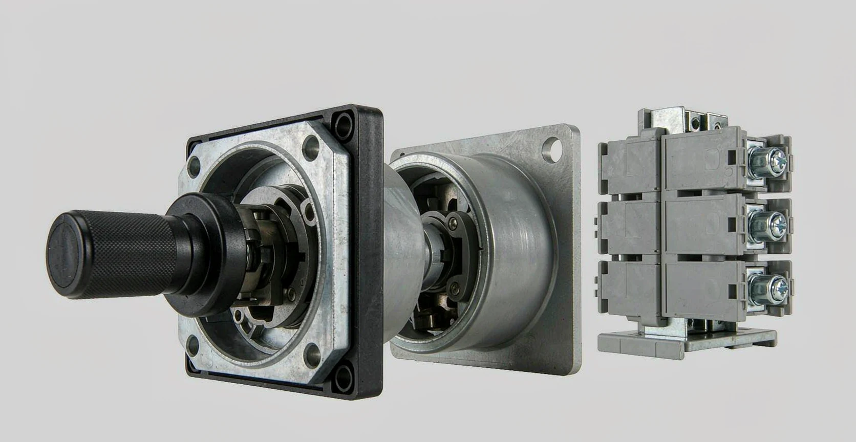
- Panel mounting — the default: a central shaft through a round hole, fixed by screws at the corners of the front plate. Gives the most mechanical support for a large handle.
- Single-hole mounting — one round hole, retained from behind. Faster to fit, and the usual choice where panel space is tight.
- DIN rail mounting — a base-mounted version that clips to TS35 rail, used where the switch is inside the enclosure rather than on the door.
- Door interlock — a base-mounted switch with a mechanism that prevents the door opening while the switch is on, or prevents the switch closing while the door is open. Common on machine and pump panels.
- Sealed enclosure — a factory-fitted IP65 box for outdoor, wash-down or dusty locations.
Ingress protection follows the enclosure, not the switch mechanism. A standard panel-mount switch behind a gasketed door reaches the door’s rating; the same switch in an open frame does not. For outdoor pump and HVAC work, the selection logic is set out in choosing a rotary isolator switch for pumps and HVAC, which covers the enclosure and lock-off side in more depth.
A Six-Step Selection Sequence
Working through these in order prevents the most common re-ordering cycle, which starts with a catalogue picture and ends with a switch that cannot break the load.
- Define the function. Mode selection, load switching, isolation, source transfer, or step selection. One switch can do only one of these well.
- Count the circuits. Poles for phases and neutral, plus any auxiliary contacts the control circuit needs.
- Fix the positions and the angle. How many detents, whether one of them must be an off position, and whether the handle must be readable at a glance.
- Set the load and the category. Use the AC-21, AC-22 or AC-23 current for the actual load, and confirm the A or B suffix against how often the switch will be operated.
- Choose the mounting. Panel, single hole, DIN rail, door interlock or sealed box, plus the IP requirement of the location.
- Add the accessories. Auxiliary contacts for status feedback, padlock hasp, key operation, warning plate, and the terminal shroud if the panel is accessible.
At the end of step six you should be holding a model string rather than a description. If a supplier cannot turn the six answers into a code, the datasheet is incomplete.
Where Rotary Switch Selection Usually Goes Wrong
- Buying on the headline current. A 63 A AC-21 rating can fall to 32 A or lower under AC-23 at the same voltage. The two ratings are different products for practical purposes.
- Assuming a selector switch is a cam switch. If the drawing shows a sequence, the contact chart decides the part, not the handle style.
- Ignoring break-before-make on a changeover. The failure is not visible on the bench; it appears as a flash or a tripped upstream device the first time the operator transfers under load.
- Using an isolator as a load-break switch. AC-20 devices have no arc control. Opening one under load damages the contacts and, on a metal-enclosed unit, can be dangerous.
- Forgetting the neutral pole. A three-phase load with a switched neutral needs four poles; two separate devices defeat the single isolation point.
- Specifying the angle after the panel is drilled. The angle determines the handle arc and the space it sweeps. Changing it later means a new front plate.
FAQ
What is the difference between a rotary switch and a cam switch?
A rotary switch is the general family: a shaft turned by a handle to select a position. A cam switch is a rotary switch whose contacts are operated by shaped cams in a defined sequence. Every cam switch is a rotary switch; not every rotary switch has a contact sequence worth describing.
Can a rotary switch be used as a main isolator?
Only if it is a switch-disconnector rated for the duty. A pure disconnector is limited to no-load operation. For a main isolator that also breaks running current, specify an AC-23A switch-disconnector and confirm the isolating function in the open position.
What does AC-23A mean on a rotary switch?
It means the device was tested for motor and highly inductive loads (AC-23) and is verified for frequent operation (suffix A). The rated current quoted for AC-23A is lower than the same device’s AC-21 rating.
How many positions can a rotary switch have?
Two to twelve is the practical range, with 30° or 45° between detents on the higher counts. Beyond four or five positions the handle arc becomes large and the panel label has to be designed around it.
Do I need break-before-make or make-before-break?
Break-before-make for any source transfer or changeover, so two supplies are never connected. Make-before-break only where the circuit must not be interrupted, such as a current transformer secondary. Do not specify make-before-break on a changeover without checking what it connects together.
Is a 4-pole switch needed for a single-phase load?
No. A single-phase load needs two poles at most, line and neutral. Four poles are for three-phase plus neutral, or for switching two separate single-phase circuits through one handle.
Turning the Selection Into a Model Code
Rotary switch types are easier to separate, and to order, once the decision order is fixed: function first, then circuits, then positions and angle, then load category, then mounting. Most of the cost of a wrong order is not the switch itself but the panel rework behind it.
Cantak builds the LW26 series from 10 A to 315 A in panel, single-hole, DIN rail and door-interlock versions, with the contact chart supplied per position, and the LW40 multilayer range for machine control where several circuits have to switch in sequence on one shaft. Both are listed with their pole and position options on the LW26 series rotary switch and LW40 series rotary switch pages.
If a contact chart does not yet exist for the sequence you need, send the switching diagram with the pole count, the positions and the load category, and our engineers will confirm the cam arrangement before you order. The full range, including the isolator and button ranges that share the same panel standard, is on the product catalogue.