







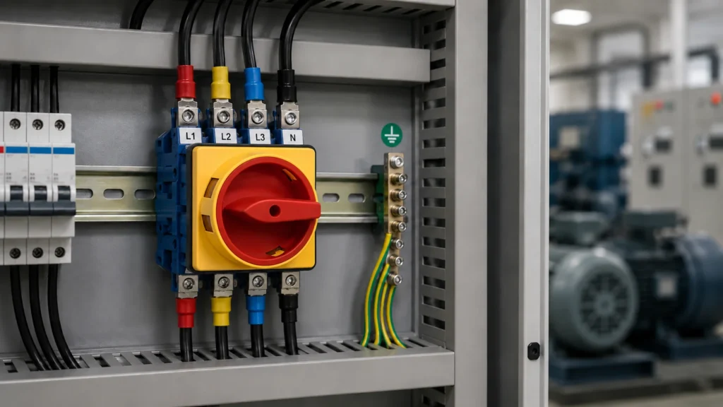
Un schéma de câblage d'un sectionneur triphasé aide les installateurs à identifier les raccordements corrects pour les phases L1, L2 et L3, le neutre, la terre de protection et les contacts auxiliaires. Un câblage correct est essentiel pour garantir une mise hors tension en toute sécurité, un fonctionnement fiable des équipements et faciliter la maintenance.
Les sectionneurs triphasés sont généralement installés dans les tableaux de commande, les moteurs, les pompes, les systèmes de chauffage, de ventilation et de climatisation (CVC), les tableaux de distribution et les machines industrielles. En fonction du système électrique, le sectionneur peut présenter une configuration à 3 pôles pour les conducteurs triphasés ou une configuration à 4 pôles qui déconnecte également le conducteur neutre.
Ce guide explique comment lire le schéma de câblage d'un sectionneur triphasé, comment distinguer les bornes d'entrée des bornes de sortie, et comment câbler le sectionneur en toute sécurité.
Avertissement de sécurité : L'installation électrique doit être réalisée par du personnel qualifié, conformément aux instructions du fabricant de l'interrupteur et à la réglementation électrique en vigueur. Veillez à toujours mettre l'installation hors tension, à la verrouiller et à vérifier l'absence de tension avant de commencer les travaux. Les directives de l'OSHA exigent de vérifier que la mise hors tension est effective avant de commencer les opérations de maintenance.
Qu'est-ce qu'un sectionneur triphasé ?
A sectionneur triphasé Un interrupteur est un dispositif de commutation à commande manuelle servant à déconnecter un circuit triphasé de sa source d'alimentation.
Lorsque la poignée est placée en position « OFF », les contacts internes se séparent, créant ainsi un point d'isolation entre l'alimentation entrante et la charge sortante. Selon le modèle, la poignée peut également être verrouillée en position « OFF » afin de réduire le risque de remise sous tension accidentelle pendant les opérations de maintenance.
Parmi les applications courantes, on peut citer :
- Moteurs industriels
- Pompes à eau
- Équipements de chauffage, de climatisation et de ventilation
- Compresseurs
- Machines-outils
- Tableaux de distribution
- Systèmes solaires et énergétiques
- Armoires de commande industrielles
Un sectionneur ne doit pas être considéré d'emblée comme un disjoncteur. Un disjoncteur ou un fusible assure généralement une protection contre les surcharges et les courts-circuits, tandis que le sectionneur sert de point de déconnexion contrôlé.
Certains produits sont classés dans la catégorie interrupteurs-sectionneurs et peuvent être homologués pour établir ou couper des courants de charge spécifiés. La capacité d'un produit donné à commuter un moteur ou une autre charge dépend de sa tension nominale, de son courant nominal, de sa catégorie d'utilisation, de la conception de ses contacts et des spécifications du fabricant.
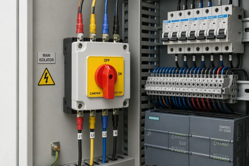
Comprendre le schéma de câblage à quatre pôles
Insérez ici l'image corrigée intitulée “ Schéma de câblage d'un sectionneur triphasé à 4 pôles ”.
Le schéma ci-contre représente une configuration à quatre pôles. Les quatre conducteurs commutés sont les suivants :
- L1
- L2
- L3
- Neutre
Le conducteur de terre de protection est raccordé à une borne de mise à la terre dédiée à l'intérieur du boîtier et n'est pas commuté par les contacts du sectionneur.
Ce schéma a pour but d'expliquer la structure générale du câblage. Les couleurs réelles des conducteurs, l'emplacement des bornes, leur numérotation ainsi que les sens d'entrée et de sortie peuvent varier selon les pays et les modèles de produits.
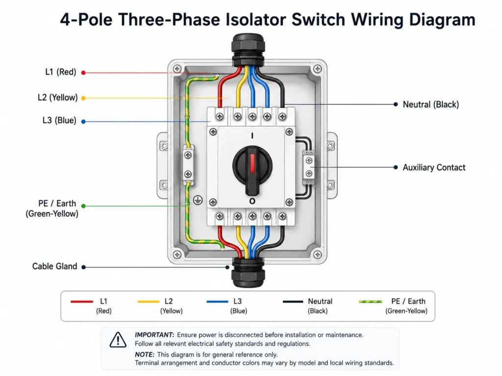
Principaux éléments représentés sur le schéma
| Composant | Fonction |
|---|---|
| L1, L2 et L3 | Trois conducteurs de phase acheminant le courant vers la charge |
| Neutre | Conducteur de retour utilisé dans les systèmes triphasés à quatre fils concernés |
| Éducation physique / Sciences de la Terre | Conducteur de protection relié à la mise à la terre du boîtier et de l'équipement |
| Principaux terminaux | Raccorder les conducteurs d'alimentation entrants et les conducteurs de charge sortants |
| Poignée rotative | Actionne simultanément tous les poteaux principaux |
| Contact auxiliaire | Envoie des signaux d'état ou de verrouillage à un circuit de commande |
| Presse-étoupe | Permet de fixer le câble et d'assurer la protection du boîtier |
| Annexe | Protège l'interrupteur contre les contacts, la poussière, l'humidité et les chocs |
Câblage d'un sectionneur tripolaire par rapport à celui d'un sectionneur tétrapolaire
Le nombre de pôles requis dépend du système électrique et de la nécessité ou non de déconnecter également le conducteur neutre.
| Configuration | Changement de chef d'orchestre | Utilisation courante |
|---|---|---|
| sectionneur tripolaire | L1, L2 et L3 | Charges triphasées ne nécessitant pas de commutation du neutre |
| isolateur à 4 pôles | L1, L2, L3 et N | Systèmes triphasés à quatre fils nécessitant une isolation du neutre |
| isolateur bipolaire | Phase et neutre | Systèmes monophasés |
| isolateur unipolaire | Un chef d'orchestre | Contrôle limité ou applications spécialisées |
Interrupteur-sectionneur tripolaire
Un sectionneur tripolaire ouvre simultanément les trois conducteurs de phase. Il est couramment utilisé avec les moteurs triphasés et d'autres charges triphasées équilibrées qui ne nécessitent pas de raccordement au neutre.
Le neutre, lorsqu'il est présent ailleurs dans le circuit, ne passe pas par l'interrupteur tripolaire.
Interrupteur-sectionneur à quatre pôles
Un sectionneur à quatre pôles coupe simultanément les phases L1, L2, L3 et le neutre. Il peut être utilisé lorsque la conception du réseau, les exigences techniques des équipements ou la réglementation locale imposent l'isolation du neutre en aval.
Le pôle neutre doit faire partie d'un produit spécialement conçu pour cette application. Il ne doit pas être improvisé en utilisant un contact sans rapport avec celle-ci ou un contact auxiliaire.
La prise de terre de protection n'est pas commutée
Le conducteur de protection (PE) ou de terre doit rester connecté en permanence à l'équipement et au boîtier.
Il ne passe pas par les contacts normalement utilisés pour la mise sous tension/hors tension du sectionneur. Il est plutôt raccordé à une borne de terre dédiée ou à une barre de mise à la terre à l'intérieur de l'armoire.
Comment câbler un sectionneur triphasé
Les étapes suivantes décrivent la procédure générale d'installation. Privilégiez toujours le schéma de câblage et les instructions fournies avec le modèle précis de l'interrupteur.
Étape 1 : Vérifier les conditions de candidature
Avant l'installation, vérifiez les éléments suivants :
- Tension du système
- Fréquence
- Courant à pleine charge
- Courant de démarrage
- Nombre de pôles
- Type de chargement
- Catégorie d'utilisation
- Indice de protection requis pour le boîtier
- Section du câble
- Environnement d'installation
- Nécessité de contacts auxiliaires
- Nécessité d'une poignée verrouillable
L'intensité nominale indiquée sur l'interrupteur ne doit pas être considérée comme le seul critère de sélection. Les charges de moteur, les charges résistives, les charges inductives et les applications de distribution peuvent nécessiter des capacités de commutation différentes.
Un interrupteur adapté à une application peut ne pas convenir à une autre application présentant le même courant nominal.
Étape 2 : Débranchez et sécurisez toutes les sources d'énergie
Déconnectez le dispositif de protection en amont et mettez hors tension toute source susceptible d'alimenter le circuit.
Mettez en place les dispositifs de verrouillage et d'étiquetage requis. Un sectionneur électrique verrouillable constitue l'un des dispositifs reconnus permettant d'isoler l'énergie, mais la procédure complète de contrôle de l'énergie doit tout de même être respectée.
Avant de toucher des conducteurs :
- Identifiez toutes les sources d'alimentation possibles.
- Ouvrez le disjoncteur ou le dispositif de coupure situé en amont.
- Mettre en place des mesures de verrouillage et d'étiquetage.
- Libérer ou retenir l'énergie emmagasinée.
- Utilisez un équipement de test adapté pour vérifier l'absence de tension.
- Vérifiez que le testeur fonctionne correctement.
Le fait de mettre un commutateur en position « OFF » ne constitue pas, en soi, une preuve suffisante que tous les conducteurs sont hors tension.
Étape 3 : Identifier les bornes de ligne et de charge
Vérifiez le marquage des bornes et le schéma du produit.
Les marques courantes peuvent inclure :
- LINE et LOAD
- ENTRÉE et SORTIE
- L1, L2, L3 et N
- T1, T2, T3 et N
- Paires de bornes numérotées
- Flèches indiquant les directions d'arrivée et de départ
Certains modèles de commutateurs rotatifs peuvent permettre le raccordement à l'alimentation par l'un ou l'autre côté, tandis que d'autres produits imposent une orientation bien précise de la ligne et de la charge.
Ne partez pas du principe que les bornes du haut correspondent toujours à l'alimentation d'entrée. Respectez les indications figurant sur l'appareil et la documentation technique du modèle choisi.
Étape 4 : Montage du boîtier
Installez le boîtier sur une surface stable et accessible, à proximité de l'équipement qu'il commande.
Le poste sélectionné doit :
- Veillez à ce que la poignée puisse bouger librement
- Veillez à ce que l'accès au terminal reste pratique
- Évitez toute chaleur excessive et toute vibration
- Éviter que l'eau ne s'accumule autour des passages de câbles
- Rendre le commutateur visible pour le personnel de maintenance
- Prévoir suffisamment d'espace pour permettre une courbure des câbles en toute sécurité
- Autoriser le verrouillage lorsque cela est nécessaire
Pour les environnements extérieurs, poussiéreux, humides ou industriels, choisissez un boîtier doté d'un indice de protection IP adapté.
Étape 5 : Installez les presse-étoupes
Utilisez des presse-étoupes adaptés :
- Diamètre extérieur du câble
- Dimensions d'entrée du boîtier
- Protection des droits de propriété intellectuelle requise
- Exigences relatives à la résistance mécanique à l'arrachement
- Conditions environnementales
Le presse-étoupe doit enserrer et assurer l'étanchéité de la gaine extérieure du câble. Il ne doit pas exercer de contrainte excessive sur les conducteurs isolés individuels.
Les ouvertures inutilisées du boîtier doivent être obturées à l'aide de bouchons d'étanchéité adaptés.
Étape 6 : Raccorder le conducteur de terre de protection
Raccordez le conducteur PE à la borne de terre prévue à cet effet à l'intérieur du boîtier.
En cas d'utilisation d'un boîtier métallique, veillez à ce que celui-ci et toutes les parties conductrices exposées soient correctement reliés à la terre, conformément à la réglementation en vigueur.
Le conducteur de terre doit :
- Clairement identifié
- Sécurisé sur le plan mécanique
- Protégé contre les dommages
- Acheminé sans passer par les contacts de commutation
- Assez long pour éviter toute tension au niveau du raccordement
La connexion à la terre de protection ne doit pas dépendre de la position de l'interrupteur (marche ou arrêt).
Étape 7 : Raccorder les conducteurs de phase d'alimentation
Raccordez l'alimentation triphasée d'entrée aux bornes de ligne prévues à cet effet :
- L1 vers la borne de la première phase
- L2 vers la borne de la deuxième phase
- L3 vers la borne de la troisième phase
Pour un interrupteur à quatre pôles, raccordez le neutre d'entrée au pôle neutre prévu à cet effet.
Veillez à respecter une identification cohérente des phases tout au long de l'installation. Les couleurs des conducteurs de phase varient selon les normes régionales ; le schéma du produit ne doit donc pas être considéré comme la seule référence pour le choix de la couleur des conducteurs.
Utilisez des cosses, des embouts ou des méthodes de préparation des conducteurs adaptés lorsque la conception des bornes l'exige.
Étape 8 : Raccorder les conducteurs de sortie
Raccordez les bornes de sortie correspondantes aux équipements en aval :
- Sortie L1 vers la connexion L1 de la charge
- Sortie L2 vers la connexion L2 de la charge
- Sortie L3 vers la connexion L3 de la charge
- Connexion du neutre de sortie au neutre de la charge lors de l'utilisation d'un modèle à quatre pôles
Conserver le même ordre des phases entre l'entrée et la sortie.
Sur les moteurs triphasés, un ordre des phases incorrect peut inverser le sens de rotation. Vérifiez le sens de rotation requis lors de la mise en service et suivez la procédure indiquée par le fabricant de l'équipement avant de modifier les branchements des phases.
Étape 9 : Raccordement du contact auxiliaire
Un contact auxiliaire est un contact distinct à faible intensité, relié mécaniquement au mécanisme du sectionneur.
Il peut être utilisé pour :
- Indication de l'état MARCHE/ARRÊT
- Signaux d'entrée de l'automate programmable
- Surveillance à distance
- Voyants lumineux du tableau de commande
- Verrouillage électrique
- Circuits d'alarme
- Logique de commande des contacteurs
Les bornes auxiliaires peuvent être identifiées à l'aide de désignations telles que :
- NO : Normalement ouvert
- NC : normalement fermé
- COM : Commun
- 13-14
- 21-22
Le contact auxiliaire ne doit pas être utilisé en remplacement de l'un des pôles d'alimentation principaux. Ses intensités et tensions nominales sont généralement bien inférieures à celles des contacts principaux.
Vérifiez si le contact change d'état avant, en même temps ou après les contacts principaux. Ce décalage temporel peut avoir une incidence sur les fonctions de verrouillage et de surveillance.
Étape 10 : Serrez et vérifiez tous les raccords
Serrez chaque borne au couple indiqué par le fabricant.
Un couple insuffisant peut entraîner :
- Augmentation de la résistance de contact
- Chauffage localisé
- Chute de tension
- Fonctionnement intermittent
- Dommages irréversibles
- Risque d'incendie
Un couple trop élevé peut endommager la borne, le conducteur, le boîtier ou le filetage.
Après le serrage :
- Vérifiez qu'aucun fil de cuivre nu ne soit exposé inutilement.
- Vérifiez qu'aucune isolation de conducteur n'est coincée à l'intérieur de la zone de serrage.
- Veillez à ce que les conducteurs n'exercent pas de traction sur les bornes.
- Vérifiez les étiquettes des phases et l'identification des bornes.
- Veillez à séparer le câblage de commande du câblage d'alimentation lorsque cela est nécessaire.
- Vérifiez que les presse-câbles sont bien serrés et étanches.
Étape 11 : Effectuer les contrôles mécaniques et électriques
Avant de mettre le système sous tension, vérifiez :
- Puissance nominale correcte du commutateur
- Nombre correct de pôles
- Raccords corrects des lignes et des charges
- Connexion à la terre en continu
- Séquence de phases correcte
- Raccordement correct du neutre
- Fonctionnement correct des contacts auxiliaires
- Couple de serrage correct des bornes
- Couvercle de boîtier sécurisé
- Mouvement de la poignée sans entrave
- Indication claire « ON » et « OFF »
- Fonction de verrouillage, le cas échéant
Les essais de continuité et d'isolation doivent être effectués à l'aide d'équipements et selon des procédures d'essai appropriés.
Ne mettez pas l'installation sous tension avant que l'inspection n'ait confirmé que le circuit est correctement monté.
Comment fonctionne un contact auxiliaire ?
Le contact auxiliaire change d'état lorsque l'on actionne la poignée du sectionneur.
Par exemple, un contact auxiliaire normalement ouvert peut se fermer lorsque le sectionneur atteint la position « ON ». Un système de commande peut alors utiliser ce signal pour allumer un voyant ou confirmer que l'interrupteur principal a été actionné.
Un contact normalement fermé peut s'ouvrir lorsque le sectionneur est mis sous tension ou se fermer lorsqu'il est mis hors tension, selon la configuration du produit.
Parmi les exemples courants, on peut citer :
Indication d'état
Un voyant lumineux indique si le sectionneur est en position « ON » ou « OFF ».
Surveillance des automates programmables
Le contact auxiliaire envoie un signal à contact sec à un automate programmable industriel (API) ou à un système de surveillance.
Emboîtement
Le circuit de commande empêche tout autre dispositif de fonctionner tant que le sectionneur n'est pas dans la position requise.
Alarme à distance
Un panneau de surveillance déclenche une alarme lorsque le sectionneur s'ouvre de manière inattendue.
Il convient de vérifier le schéma de connexion des contacts auxiliaires lors de la mise en service, plutôt que de se fier uniquement à la position physique des bornes.
Où utilise-t-on les sectionneurs triphasés ?
Les isolateurs triphasés sont généralement installés dans :
Systèmes de moteurs et de pompes
Un sectionneur local permet au personnel de maintenance de couper l'alimentation à proximité du moteur, de la pompe, du ventilateur ou du compresseur.
Équipements de chauffage, de ventilation et de climatisation
Les ventilateurs, les climatiseurs et les systèmes de circulation d'eau nécessitent souvent un sectionneur d'entretien facilement accessible.
Machines industrielles
Un isolateur rotatif permet d'identifier clairement la position de fonctionnement et peut faciliter les procédures de mise hors service des machines.
Panneaux de commande
Les sectionneurs montés en armoire peuvent servir de sectionneur d'entrée principal pour les armoires de commande et les systèmes d'automatisation.
Installations en extérieur
Les isolateurs en caisson peuvent être choisis pour résister à la poussière, à la pluie, à l'humidité ou à d'autres conditions environnementales difficiles.
Equipement OEM
Les fabricants de machines peuvent personnaliser les intensités nominales, les poignées, les cotes de montage, les marquages, les contacts auxiliaires, les boîtiers et le marquage de la marque.
Choisir le bon sectionneur
Avant de passer commande, veuillez fournir au fournisseur :
- Tension nominale du réseau
- Courant nominal de fonctionnement
- Nombre de pôles
- Type de chargement
- Puissance du moteur, le cas échéant
- Catégorie d'utilisation
- Fréquence de fonctionnement
- Indice de protection IP requis
- Installation à l'intérieur ou à l'extérieur
- Modèle à montage sur panneau ou en boîtier
- Exigences relatives aux contacts auxiliaires
- Exigences relatives aux cadenas
- Dimensions des entrées de câbles
- Certifications requises
- Quantité estimée de la commande
Cantak répertorie ses Interrupteur d'isolement série LW30 dans la plage de 20 A à 175 A. Le site web précise également que les interrupteurs LW30 et LW30B conviennent à des applications telles que les équipements de ventilation, les systèmes de climatisation, les systèmes de pompage d’eau et certaines configurations de commande de moteurs à courant alternatif. Le choix final doit toujours être effectué en fonction des caractéristiques techniques exactes indiquées dans le catalogue et des conditions d’utilisation.
Cantak propose également des options OEM et ODM couvrant la tension nominale, le courant nominal, la conception des boutons, les cotes de montage, les angles de rotation, les matériaux, les configurations IP65/IP67, l'étiquetage, la personnalisation de la marque et l'emballage.

Vous avez besoin d'un sectionneur triphasé ?
Cantak fournit des sectionneurs rotatifs destinés aux tableaux de commande, aux machines industrielles, aux systèmes de ventilation, aux pompes et aux équipements OEM.
Veuillez nous indiquer le courant, la tension, la configuration des pôles, l'application, l'indice de protection et la quantité souhaités afin de recevoir une recommandation de modèle adapté ainsi qu'un devis.
Conclusion
Pour réaliser correctement le câblage d'un sectionneur triphasé, il faut commencer par choisir le produit adapté au système électrique et à la charge.
Un modèle tripolaire coupe les phases L1, L2 et L3, tandis qu'un modèle tétrapolaire coupe également le neutre. Le conducteur de terre de protection reste connecté en permanence à l'équipement et au boîtier.
Lors de l'installation, les techniciens doivent identifier les bornes d'alimentation et de charge appropriées, respecter l'ordre des phases, raccorder le neutre uniquement via un pôle approprié, raccorder correctement le conducteur de terre et vérifier la logique des contacts auxiliaires.
Il est avant tout essentiel qu'un sectionneur soit utilisé dans le cadre d'un système complet de sécurité électrique. Des disjoncteurs ou des fusibles adaptés restent nécessaires pour assurer la protection contre les surcharges et les courts-circuits.
FAQ
Puis-je utiliser un sectionneur tripolaire sur un réseau avec neutre ?
Un sectionneur tripolaire ne commute que les phases L1, L2 et L3. Le fait que le neutre puisse rester connecté en permanence dépend de la conception du réseau, des exigences des équipements et de la réglementation locale. Utilisez un modèle tétrapolaire lorsque le neutre doit également être isolé.
Le fil de terre passe-t-il par le sectionneur ?
Non. Le conducteur de terre de protection est normalement raccordé directement à la borne de terre dédiée ou à la barre de mise à la terre. Il ne doit pas être commandé par les contacts principaux de marche/arrêt du sectionneur.
Un sectionneur peut-il remplacer un disjoncteur ?
Non. Un sectionneur assure la coupure électrique, mais n'offre pas nécessairement une protection automatique contre les surcharges ou les courts-circuits. Il est généralement nécessaire d'utiliser un disjoncteur ou un fusible correctement choisi.
Un sectionneur triphasé peut-il commander un moteur ?
Uniquement si l'appareil sélectionné est adapté à l'application du moteur et à la catégorie d'utilisation correspondante. Vérifiez le courant du moteur, les conditions de démarrage, la tension, la fréquence de fonctionnement et les spécifications du fabricant avant de procéder à la sélection.