Switches and Pushbutton Symbols are key to reading circuit diagrams. This article explains common symbols and their uses for easy understanding.

The “Generic Switch Symbol” in the open condition indicates that the switch is not allowing current to pass through, representing a break in the circuit.

The “Open Switch” symbol is a standard representation used to indicate that a switch is currently in the open position. An “Open Switch” acts as a break in the circuit, meaning it interrupts the electrical path and stops the flow of current through the circuit.

The “Closed switch” symbol is a general representation indicating that the switch is in the closed position, which means the circuit is complete and allows current to flow through it.

The “Thermal Magnetic Switch” symbol represents a switch that combines both electromagnetic and thermal tripping mechanisms. In the event of large current surges, the electromagnetic part of the “Thermal Magnetic Switch” instantly interrupts the circuit, while the bimetallic strip introduces a slight delay when the current gradually exceeds the set threshold.

The symbol shown denotes a “Limit Switch,” which is activated when mechanical parts or objects within a machine make contact with its actuator. “Limit Switch” devices are commonly used in control systems to detect the position or movement of machine components.

The “Telegraph Key” symbol represents a specialized electrical switch used for sending text messages in Morse code. By pressing and releasing the “Telegraph Key,” the circuit is repeatedly connected and disconnected, generating electrical pulses of different lengths—known as “dots” and “dashes”—which encode the transmitted message.

A “Differential Switch” functions by monitoring the difference between the current in the phase line and the current in the neutral line. When the “Differential Switch” detects any imbalance, often caused by a fault current, it disconnects the circuit to ensure safety.

The “Pulse Counter Switch” is controlled by a pulse counter, and it activates to switch the connected circuit whenever the pulse counter reaches a predetermined value.

The “Switch SPDT” symbol represents a single pole double throw switch, which features three terminals—one common terminal that can be connected to either of the other two terminals, allowing the circuit to switch between two different outputs.

The “Slide Switch SPDT” features a sliding actuator that moves back and forth to open or close the circuit. The symbol shown represents an SPDT (single pole double throw) slide switch, which allows the user to connect the common terminal to either of two outputs by sliding the switch.

A “Switch DPST” (Double Pole Single Throw) has two poles, allowing it to control two separate circuits simultaneously. With only one ON position, the “Switch DPST” turns both circuits ON or OFF at the same time.

The “Switch DPST One close before other” is a variation of the DPST switch where one modified pole makes contact before the other during activation. This sequential closing mechanism ensures prioritized circuit connections in applications requiring precise timing, such as safety systems or equipment needing staged power delivery.

The “Switch DPDT” (Double Pole Double Throw) is essentially two SPDT switches operated together by a single lever or actuator. This configuration allows the “Switch DPDT” to control two separate circuits at the same time, with each circuit having its own set of terminals. In either of the two positions, each circuit is connected to a different pair of terminals, enabling flexible switching between outputs for both circuits simultaneously.

The “Switch DPMT” (Double Pole Multi Throw) is designed with two poles, enabling it to control two independent circuits. Each pole of the “Switch DPMT” can be connected to multiple terminals, allowing each circuit to be switched among several different outputs.The “Switch SP4T” symbol represents a switch with a single pole and four throws, meaning it has four selectable positions. The “Switch SP4T” allows a single circuit to be connected to any one of four different terminals, providing multiple output options.

The “Switch SP4T” is a single pole, four throw switch with four selectable positions. It allows one circuit to be connected to any of four different terminals.

The “Rotary Switch” symbol represents a switch operated by a rotating knob, which turns around its axis to connect the common terminal to one of several output terminals. A “Rotary Switch” can feature multiple poles, allowing it to control several independent circuits, and can also have multiple throws for selecting among various outputs.

The “On-Delay Switch” is characterized by an immediate transition from ON (closed) to OFF (open) position, but when switching from OFF to ON, it introduces a time delay before closing the circuit. The symbol for the “On-Delay Switch” illustrates this delayed activation feature.

The “ON OFF Delay Switch ON OFF” features a time delay in both directions—whether switching from ON to OFF or from OFF to ON, the switch introduces a delay before changing its state. This ensures that the “ON OFF Delay Switch ON OFF” does not immediately respond, but instead waits for a preset period during each transition.

The “Generic Push Button Switch” symbol represents a single pole single throw (SPST) pushbutton switch equipped with an actuator. Pressing the actuator toggles the circuit ON or OFF, allowing or interrupting current flow as needed.

The “Rotary Closed Switch” symbol indicates a rotary switch that is in the closed (ON) position. This type of switch is single pole and remains in the make contact position without any automatic return feature.

The “Rotary Open Switch” symbol represents a rotary switch in the open (OFF) position, indicating that the circuit is disconnected and no current can flow through it.

The “NO Push Button” refers to a Normally Open pushbutton switch that typically stays in the open (OFF) position. When the “NO Push Button” is pressed, it temporarily closes the circuit (ON position), but once released, it returns to its default open (OFF) state.

The “NC Push Button” is a normally closed push button switch that stays in the closed (ON) position under normal conditions, allowing current to flow through the circuit. When the “NC Push Button” is pressed, it opens the circuit and switches to the OFF position, interrupting the current. Once the button is released, it automatically returns to the closed (ON) position, restoring the circuit.

The “Push Button Lockable” symbol represents a push button switch that can be locked in a selected position. While it typically returns automatically to its normal state after being pressed, the “Push Button Lockable” feature allows it to remain in the chosen position when locked.

The “Positive opening Push Button mushroom head” is a type of push button switch featuring a large, mushroom-shaped actuator. This switch is designed with a positive opening mechanism, meaning its contacts are physically forced open when the device is in its open position, ensuring reliable disconnection. The mushroom head makes it easy to operate, often used for emergency stop functions where clear and definite circuit interruption is required.

The “Positive make Contact Push Button” is a push button switch designed so that its contact closes and completes the circuit when the switch is in the corresponding closed (ON) position. This ensures a reliable connection whenever the “Positive make Contact Push Button” is pressed into the close position.

The “Timer Switch” symbol represents a switch that operates based on a preset time interval. This type of switch makes and breaks contact automatically when the timer runs out, providing a time delay function for various applications. The timing in a “Timer Switch” can be set using mechanical clockwork or electronic mechanisms, allowing the circuit to be controlled according to a scheduled period rather than manual operation.

The “Delayed Closing Switch” symbol represents a switch whose contact does not close immediately after activation but instead introduces a short time delay before completing the circuit. This delayed response ensures that the “Delayed Closing Switch” only allows current to flow after the preset delay period has elapsed.

The “Fast Closing Switch” symbol indicates a switch that immediately closes and turns ON as soon as its position is changed, allowing current to flow without any delay.

The “Delayed Opening Switch” is a type of switch whose contacts remain closed for a short period even after switching from ON to OFF. When the switch is moved to the OFF position, the “Delayed Opening Switch” introduces a time delay before its contacts actually open and disconnect the circuit, ensuring the current continues to flow for the preset delay duration before turning off.

The “Fast Opening Switch” immediately opens its contacts when actuated, quickly interrupting the circuit.

The “Push to Make Switch” symbol shows a push button in the open position. Pressing and holding the button closes the contact (ON), and releasing it returns the switch to the open state.

The “Push to Break Switch” is normally closed, keeping the circuit complete. Pressing and holding the “Push to Break” button opens the circuit, and releasing it restores the closed condition.

The “Push Button Limit Switch” is activated by the movement of machine parts or objects, and it controls circuits that manage other machine functions.

The “Push Button Double Pole Limit Switch” controls two separate circuits, breaking one while simultaneously closing the other.

The “Joystick Switch” features a lever attached to a base, and moving the stick in different directions connects various terminals. “Joystick Switch” devices are commonly used in gaming controllers and industrial equipment like cranes and trucks.

The “Push Button SPDT” is a single pole double throw push button that maintains contact (ON) in both positions. Pressing and holding the button switches the connection to the alternate terminal, and releasing it returns the contact to its original state.

The “Push Button DPDT” is a double pole double throw switch that controls two circuits. Pressing the button breaks one circuit and closes the other, and releasing it reverses the switching action.

The “Float Switch” is used to control circuits or machines based on the liquid level inside a tank. It automatically turns ON or OFF as the liquid level rises or falls.

The “Thermal Switch” operates based on temperature, activating or deactivating a circuit when a preset temperature is reached. It resets to its normal state once the temperature returns to normal.

The “NC Thermal Switch” stays closed (ON) at room temperature. If the temperature rises above a set point, it opens the circuit, and when the temperature drops back down, it closes the circuit again.

The “NO Thermal Switch” remains open at room temperature. When the temperature rises, it closes the contact (ON), and lowering the temperature returns it to the open (OFF) position.

The “Selector Switch” is a rotary switch with multiple positions, allowing it to control one or more circuits simultaneously.

The “Starter,” also called an electronic fluorescent starter, is used to gently start fluorescent lamps by preheating the cathode and sending a controlled pulse to ignite the lamp.

The “Mercury Switch” contains mercury inside a vessel between two terminals. Tilting the vessel moves the mercury, which conducts electricity and connects or disconnects the terminals. “Mercury Switch” devices are ideal for applications involving motion, such as tilting or rolling.

The “Foot Operated Switch” symbol depicts a single pole switch designed for foot control, often used to operate circuits or motors in heavy machinery. Its robust construction allows for reliable operation under foot pressure.

The “Switch DPST BBM” is a double pole single throw switch featuring a break before make mechanism, meaning it opens one circuit before closing the other.

The “Proximity Switch” is a non-contact sensor that detects objects within a close range. When an object enters its detection area, the “Proximity Switch” activates a connected circuit, such as an alarm or counter.

The “Neon Lamp Switch” is a single pole single throw switch that includes a neon lamp as an indicator to show when current is flowing through the switch.
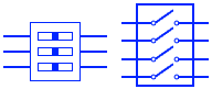
A “DIP Switch” (Dual In-line Package Switch) is a set of small manual switches grouped together in a single package with a dual in-line pin layout. These switches are designed for mounting directly onto printed circuit boards (PCBs) and are commonly used to configure settings or customize the behavior of electronic devices due to their compact size.
